Saving Those Heads

Saving Those Heads

How to Fix Destroyed Vintage Cylinder Heads

By Len Emanuelson

One of the real issues with running vintage kart motors is
that the parts are hard to find and are getting very expensive. There are a few
engines like TKM and a few IAME based engines that you can still buy new
replacement parts, but a typical cylinder head can be $250 or more. So it pays
to try to salvage what you have if you can. In most cases all that’s required
is a manual lathe and a $60 arbor from LAD.

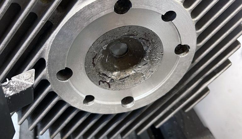
I’m no machinist, but I have a lathe, and at the rate I blow
stuff up, I fix my own engines. In this case a friend brought me a TKM 150cc
cylinder head that had been pretty well beaten up by a piston failure. As you
can see in the “before” photo, we mapped out our strategy by numbering the
sequence of the surfaces to be machined. The objective is to end up with the
squish band the same relative distance from the sealing surface as it was
before machining. Another objective is to remove the least amount of material
possible, because it is the head’s total mass that acts as a heat sink, and
keeps your air-cooled motor cooling as efficiently as possible.

Follow along as we bring this cylinder head back
to life in less than one hour of time in the shop.

Step 1

First, inspect the damage to see if the head is even repairable without welding. We decided to first machine the cylinder sealing surface (#1) .020”, the head-to-muff surface (#2) .020” second and the squish band (#3) .020” third. If the squish band did not clean up at .020” we would have started over on all three surfaces with an additional .010” cut. The object is to remove the least possible amount of material and still restore the surfaces.

Step 2

Here is the LAD cylinder head mandrel. It fits into the lathe chuck or collet and then the head screws on to the mandrel via the sparkplug threads.

Step 3 & 4

Step3
The mandrel should stick out of the lathe chuck or collet just enough to screw on the head and clear the fins. This provides the least amount of runout for accurate machining.

Step 5

We first machined the head-to-barrel sealing surface. To do this we ran the lathe in reverse (clockwise) so that we could easily see the cutting tool. Important because the tool must cut all the way into the corner of the “step” for the liner. The cylinder must be very tight on the mandrel or it will unscrew from the force of the cutting tool.

Step 6

Next we cut the surface above the muff. We ran the lathe in the normal rotation (CCW) for this operation.

Step 7

The angled squish band is machined with the “compound” part of the lathe. Foreign motors like the TKM, most Komets, etc. use approximately an 11.5-degree angle on the squish band. A good way to check the angle your compound (without the lathe running) is to touch-off the cutting tool on the inside edge of the squish band, back the tool carriage off .010” and then move the cutting tool to the outside edge of the squish band with the compound. It should be .010” away from the squish band if the compound angle is set correctly. If not adjust.

Step 8 & 9

Step8
After cutting the squish band the bowl-to-band parting line was still in pretty rough shape. We readjusted the cutting tool and took a light cut on the outside edge of the bowl area until the damaged area was gone.

Step 10

A piece of 400 grit sandpaper was used to blend the angle cuts and damage in the bowl area. Probably not how your shop teacher showed you how to do it, but as you can see in the finished photo, it works.

Step 11

The final check is to make sure the squish band is the correct diameter for your engine’s bore. We are using a 58.8mm piston, so the 58.85mm size is just about right. If your diameter is too small, cut the squish band deeper. If it is too big, cut the cylinder sealing surface some more. After you do a couple of these you’ll get the hang of juggling the dimensions for the desired results.